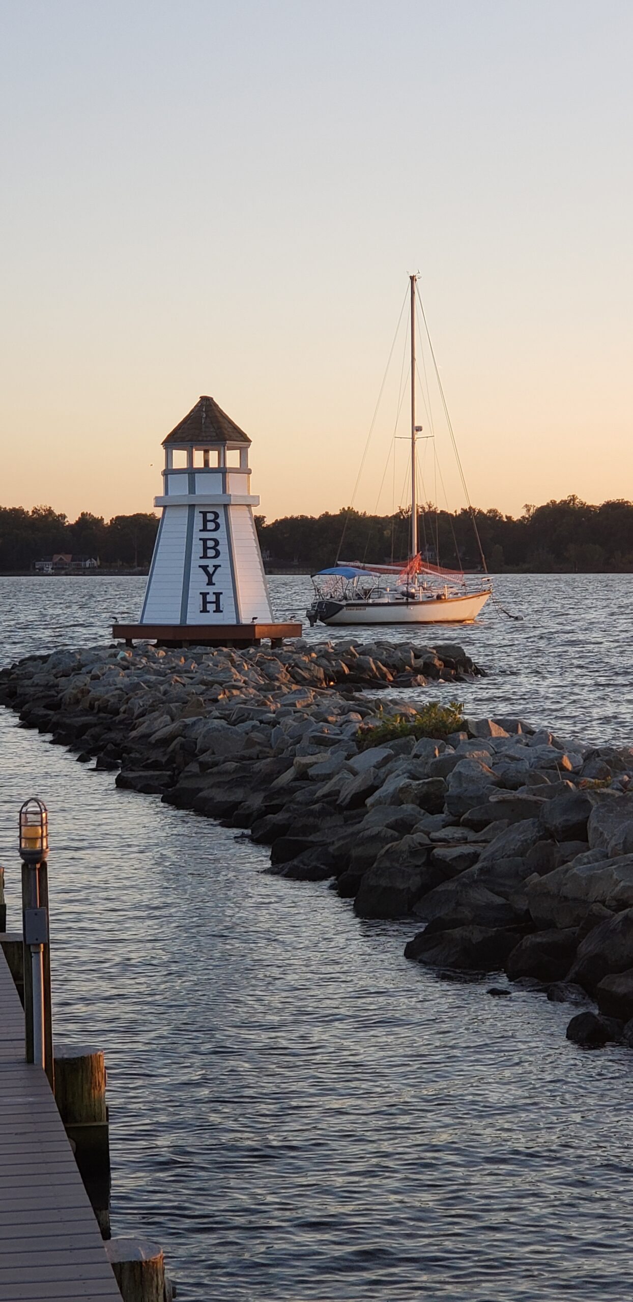
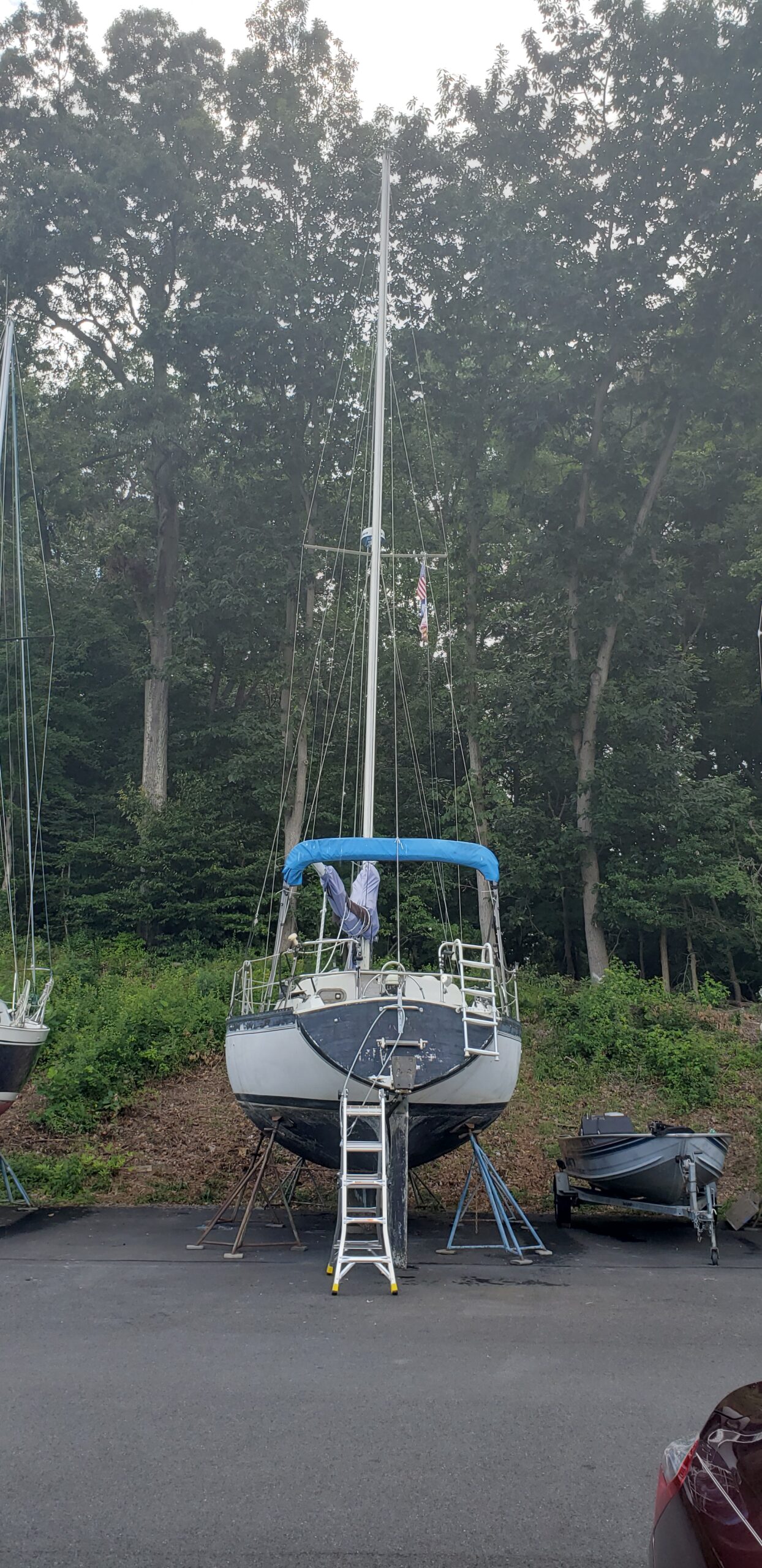
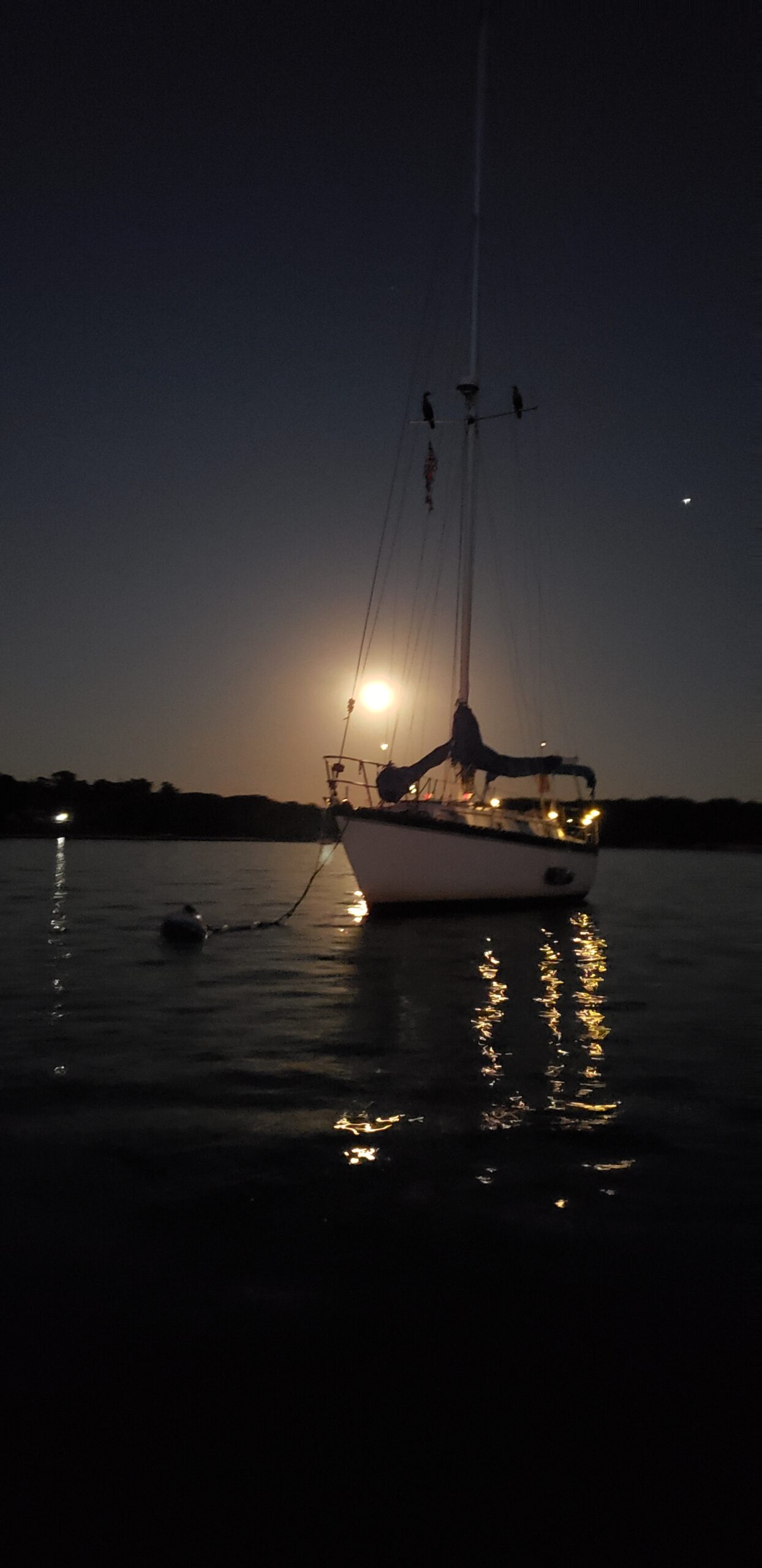
Here’s a quick list of tasks, in no particular order:
- Clean heat exchanger from engine (309)
- Establish need for an expansion tank for freshwater loop
- Get new bolts for exhaust mixing elbow installation ($) DONE
- Remove sheared bolt from engine block (517)
- Buy new engine mounts ($$$) DONE
- Clean engine compartment (BBYH)
- Move water heater into installation location (BBYH)
- Test pressure water pump(s) (309)
- Test hot water circuit without heat exchanger loop (BBYH)
- Repair louvered door to closet (517)
- Service winches (?)
- Install lens in forepeak hatch (BBYH)
- Raise mainsail (BBYH)
- Renew boom lines and pulleys (BBYH)
- Move outboard to 517 -but the outboard STARTED! (5/26/25)
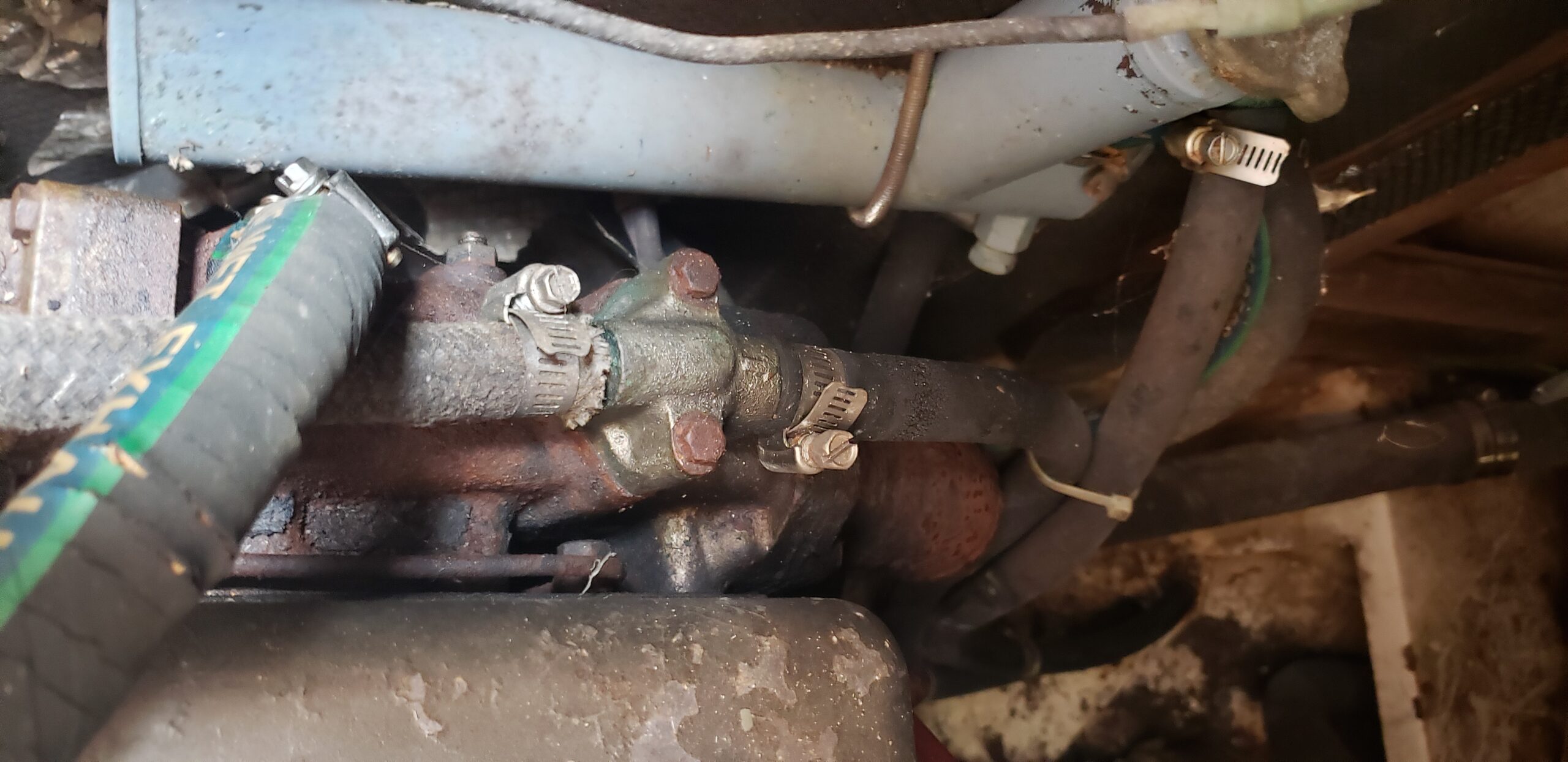
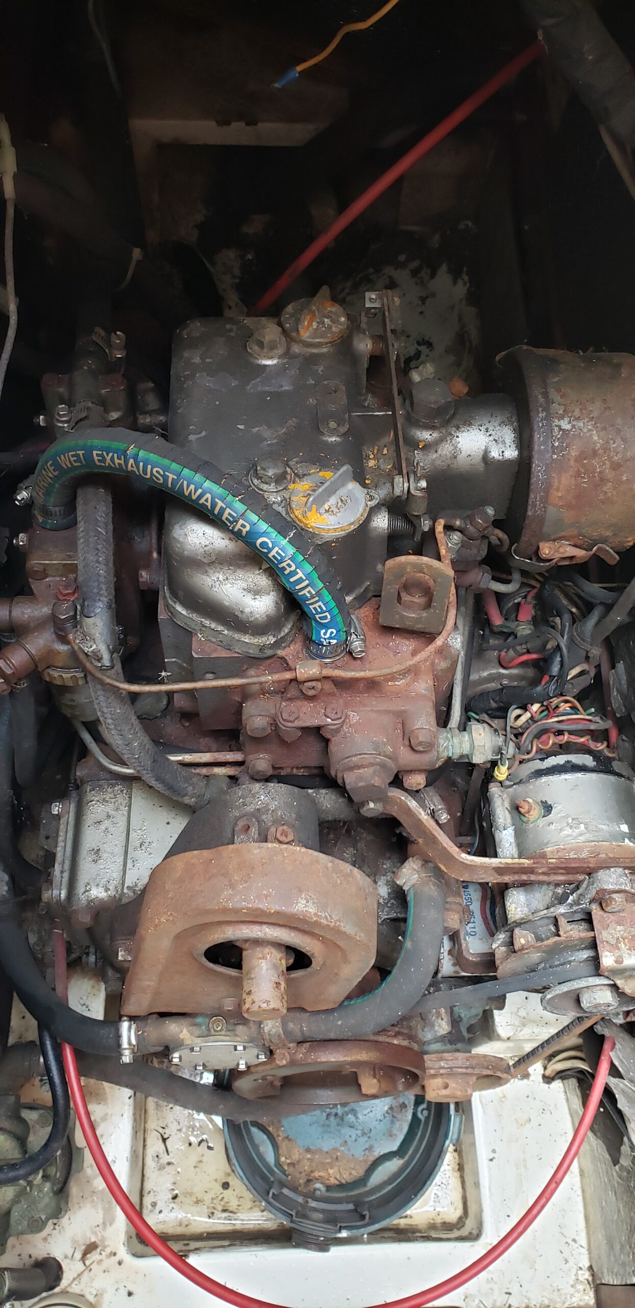
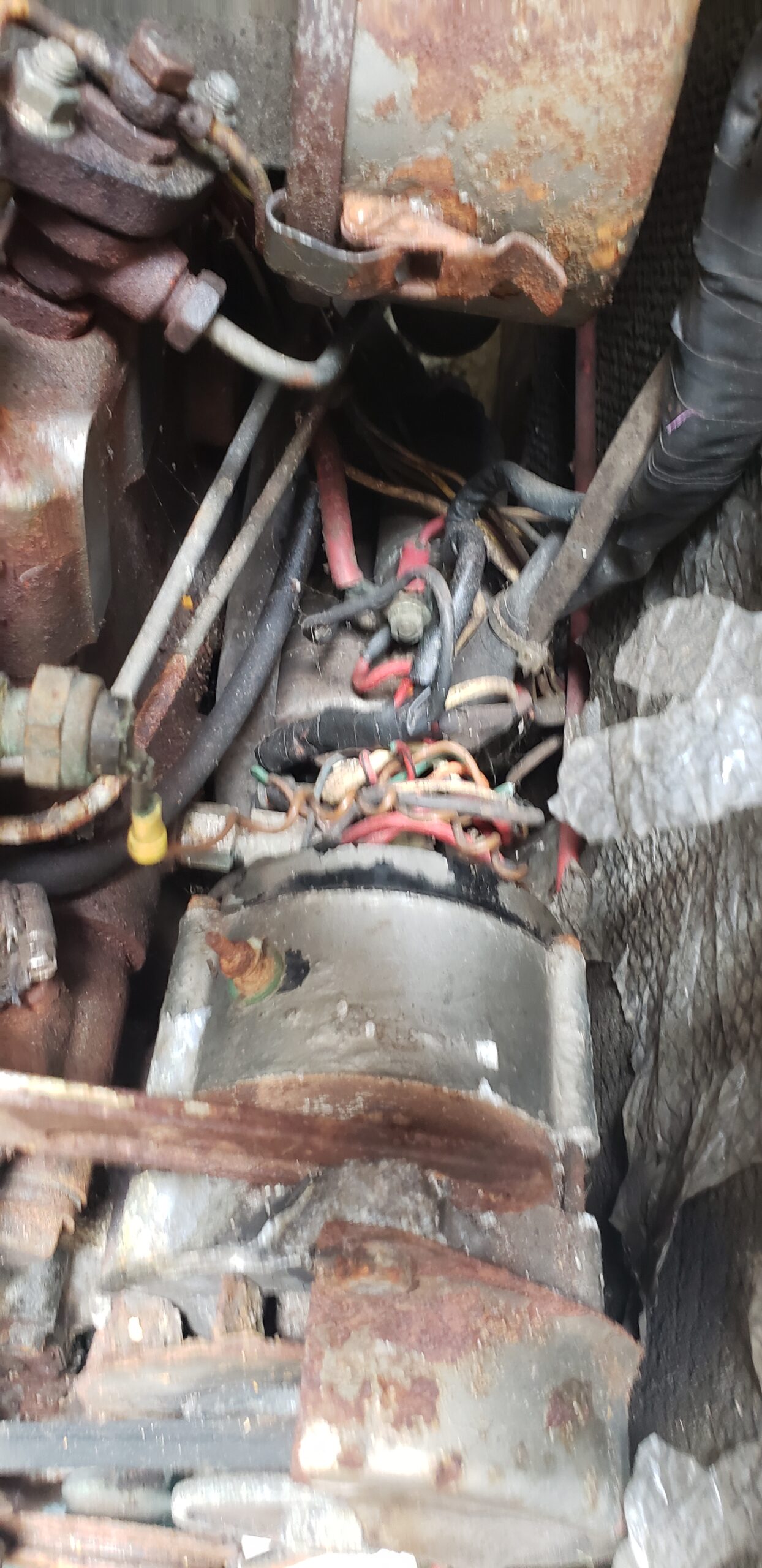
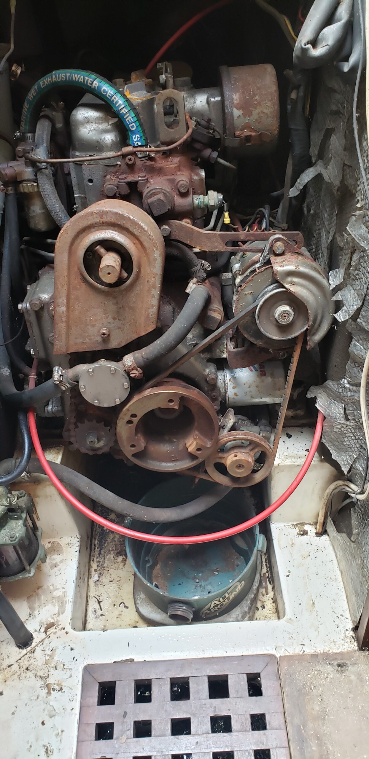
What I’m trying to understand with these pictures above is just how the fluid flow of the original setup was defined. The original raw water pump is, I believe visible at center and right, positioned just to the left and above the crankshaft pulley, while the aftermarket pump is belt-driven, below and to the right of the crankshaft pulley. In the center and right pictures above, there is a hose emerging from the floor molding at far lower left. This same hose, in this view, appears to enter the aftermarket pump directly.
Maybe the original raw water circuit was converted into the coolant circuit. It is designed to circulate water through the cylinders and exhaust, after all. In that case, the aftermarket pump now takes raw water and circulates it through the aftermarket heat exchanger. In that way, the cooling connection from the original pump through the cylinders and exhaust manifold remains undisturbed. But then that heated water must be run through the heat exchanger, and back to the original pump. possibly including an expansion tank (did they not have one in this installation, or was it removed?). Such connections would close the new “freshwater” cooling loop. The incoming raw water is then (after normal raw water filtering) run directly to the heat exchanger, and from there into the mixing elbow, and then out of the boat.
3/11/2025
In October, I visited the boat long enough to get the engine moved from the workshop to the storage unit. What an adventure! FIrst, the cart I’d arranged was pathetically too weak to support the engine adequately while rolling the whole assembly into place. So I dashed up to Harbor Freight where they still had in stock the larger dolly. The staff and I maneuvered the dolly and the engine on its wooden stand into a rented UHaul 15′ truck (with ramp) and I drove it to the unit. After about a half-hour of fiddling, I was able to roll the engine on its cart into the storage unit.
The work I can do here is the cleaning out of the heat exchanger, per the many YouTube videos on the subject. When that’s done, I’ll bring back the whole assembly in a piece of checked luggage, and commence work on setting up a test bed..
So the work in the unit will involve the removal of the broken bolt and replacing it. I believe I have all the taps dies and other extractive and clean-up devices to make that work. Once that happens, I can also complete the removal of the old elbow and the installation of the new one, probably over the long Memorial Day weekend. I would also hope to be able to construct a test stand using a starting battery, some hoses, and a few buckets and a starter circuit.
When the work there is done, I should rent a UHaul trailer along with a UHaul vehicle to pull it. It will be a much easier task to get the engine onto a low trailer than to get it up into a truck like they did with their forklift.
